Welcome to this beginner-friendly tutorial on using View Range settings in Autodesk Revit! View Range is a powerful tool that allows you to control which elements are visible in your floor plan views. By the end of this tutorial, you’ll understand how to adjust these settings to display exactly what you need in your drawings.
—
What is View Range?
In Revit, the View Range determines how much of the model is visible in a floor plan view. It defines the vertical range (height) of the view and controls which elements are cut, visible, or hidden. Think of it as a “slice” through your building model at a specific height.

—
Key Components of View Range
The View Range settings consist of four primary planes:
- Primary Range
– Top: Defines the upper limit of the view.
– Cut Plane: Defines the height at which elements are “cut” (e.g., walls, doors, windows).
– Bottom: Defines the lower limit of the view.
- View Depth: Extends below the Bottom plane to show additional elements (e.g., foundations or floor slabs).
—
Step-by-Step Guide to Adjusting View Range
Step 1: Open a Floor Plan View
- Open your Revit project.
- Navigate to the floor plan view you want to adjust.
—
Step 2: Access View Range Settings
- In the Properties palette, scroll down to the Extents section.
- Click on View Range to open the View Range dialog box.
—
Step 3: Understand the View Range Dialog Box
The dialog box will display the following fields:
– Top: Set this to the highest level you want to see in the view (e.g., the level above).
– Cut Plane: Set this to the height where elements are cut (typically 4 feet for floor plans).
– Bottom: Set this to the lowest level you want to see in the view (e.g., the current level).
– View Depth: Set this to extend below the Bottom plane if you want to see additional elements.
—
Step 4: Adjust the Settings
- Set the Cut Plane: For most floor plans, set the Cut Plane to 4 feet (1200 mm) to cut through doors and windows.
- Adjust the Top and Bottom: Set the Top to the level above and the Bottom to the current level.
- Extend the View Depth: If you want to see elements below the floor (e.g., foundations), set the View Depth below the Bottom plane.
—
Step 5: Apply and Check the Results
- Click OK to apply the settings.
- Review your floor plan to ensure the desired elements are visible.
—
Tips for Beginners
– Experiment: Don’t be afraid to adjust the settings and see how they affect your view.
– Use Defaults: Start with the default settings and tweak them as needed.
– Check Visibility Graphics: If elements are still not visible, ensure they are not hidden in the Visibility/Graphics settings.
—
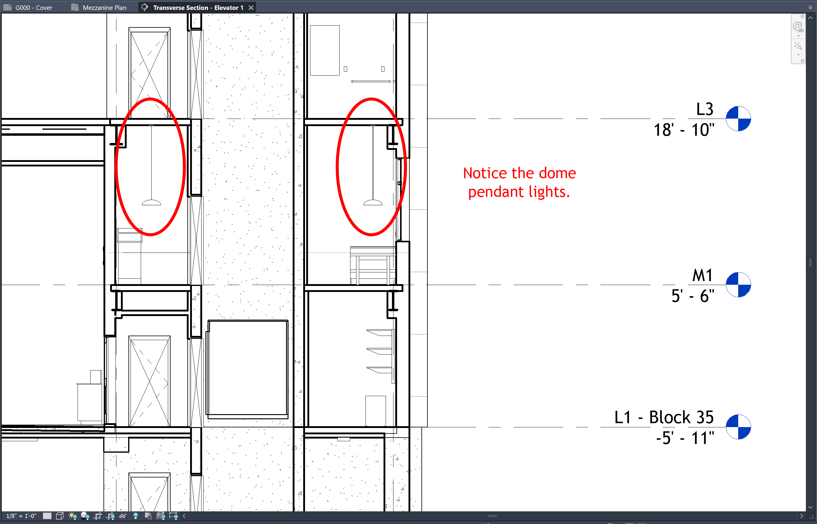
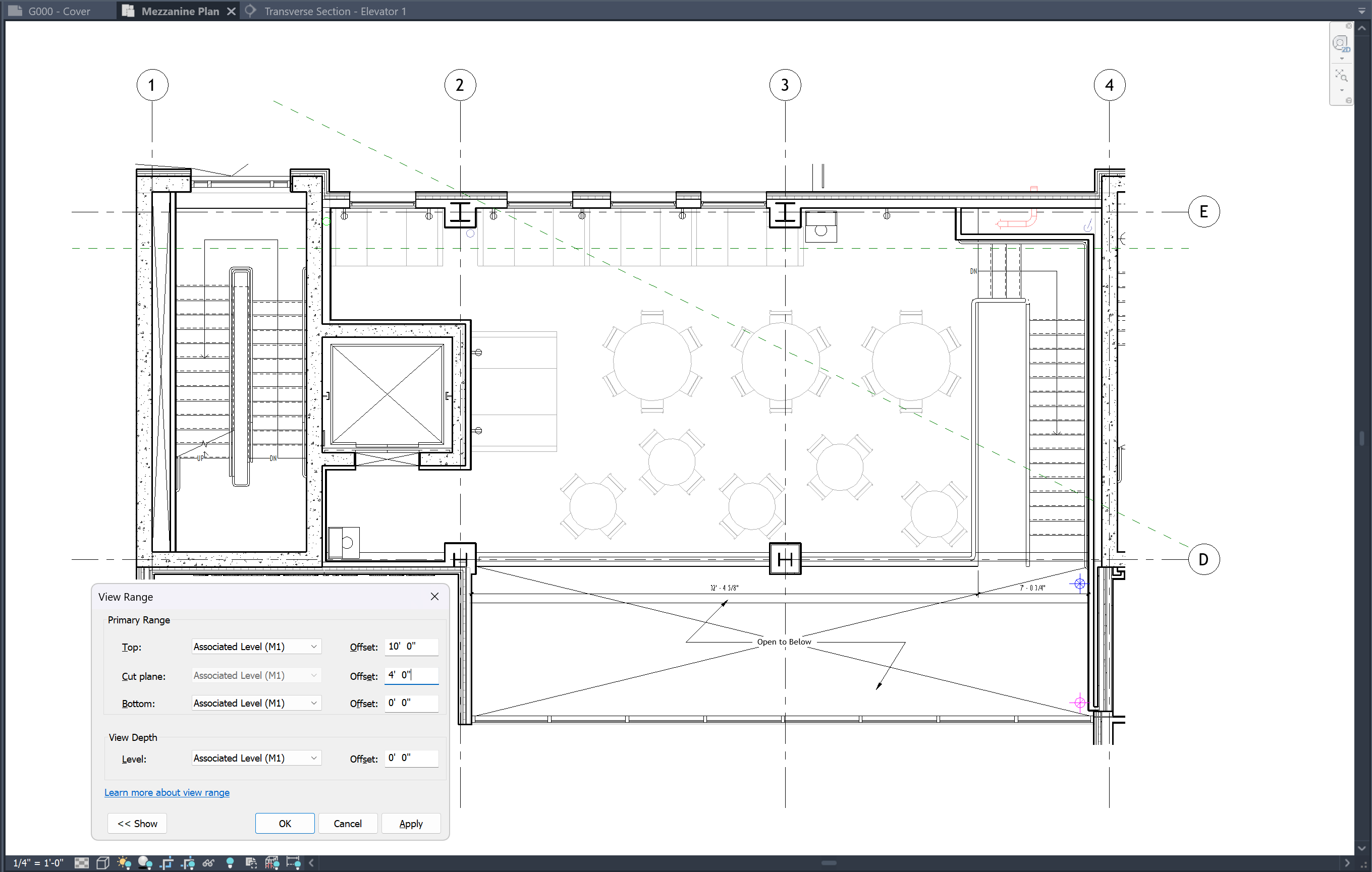
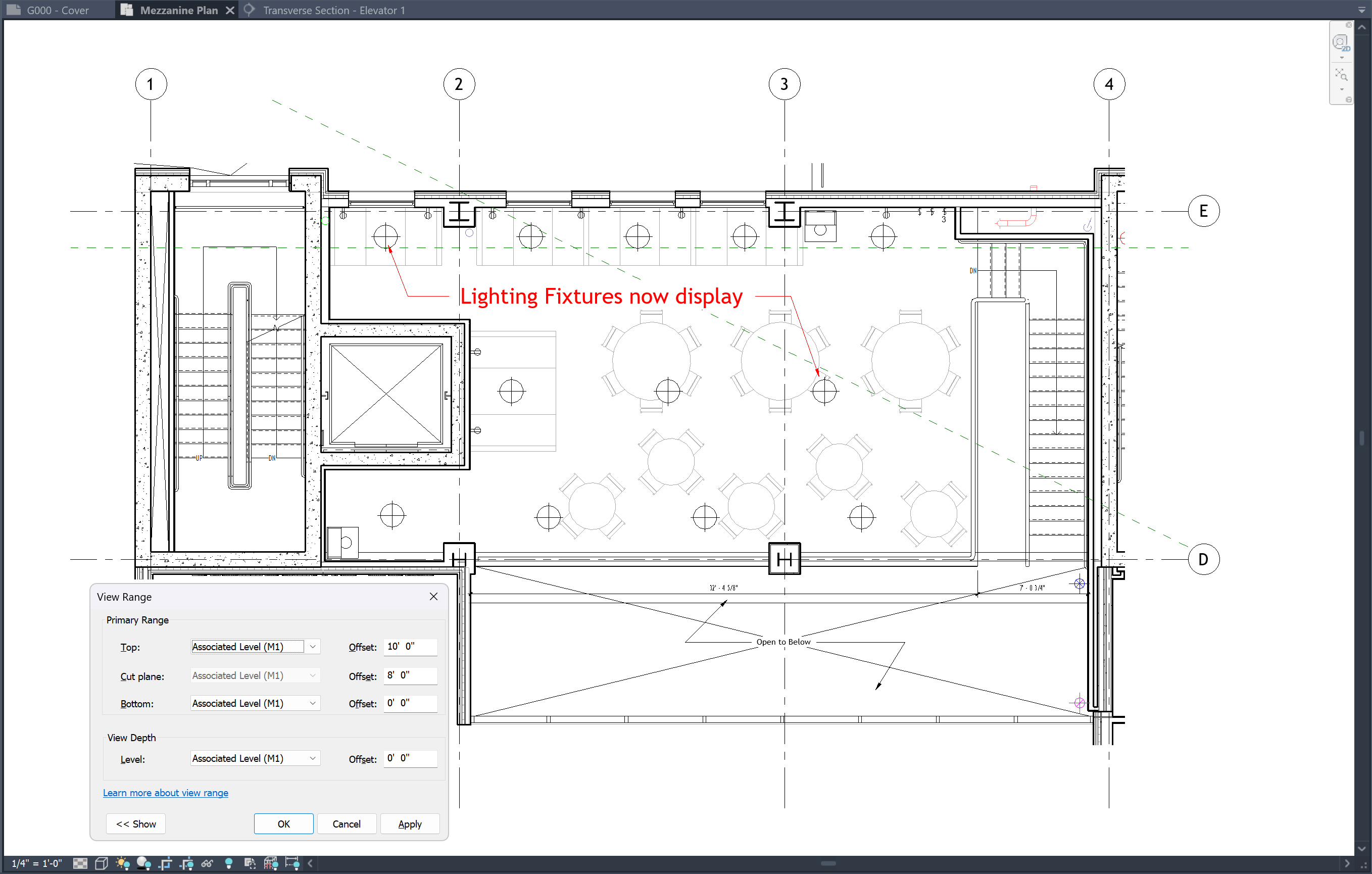
Visual Aid
The images below are an example of how the View Range dialog box looks and how it affects a floor plan view:
—
Conclusion
Mastering the View Range settings in Revit is essential for creating accurate and clear floor plan views. By following this tutorial, you should now feel confident in adjusting these settings to control the visibility of elements in your projects.
Happy modeling!
If you have any questions about Revit or access the View Range, feel free to leave a comment down below and one of our instructors can reach out.