by Alberto Freire | Oct 17, 2018 | Autodesk
Many companies have their main sheet size set to 22×34 so they can plot large, and then half scale (11×17). However, there are many companies that are required to plot 24×36. This makes plotting half-scale plans a little more difficult. That said, it is still doable. Let’s look at the steps to “plot small, when the sheet is big.”
It’s all in the Page Setup
When you go to plot, you can either modify the layout’s page setup or create a named page setup that can be applied to all your layouts and used company-wide. This is what I recommend you do. Create all the layouts and named page setups you need for all the different printers/plotters in your company’s or personal drawing template (.DWT file).
To do this, open the .DWT file, and create all the layouts you use for the different sheet sizes/plotters you plot to at your company (don’t forget to create one for .PDF files, too, you can download soda pdf support, offers a free online PDF reader, PDF creator and PDF converter).

Next, right-click on the active layout and choose Page Setup Manager from the context menu. Now, in the Page Setup Manager dialog box, you should notice a few things. First, any “line” that is surrounded by an asterisk (*) is an actual layout. In addition, any rows that are not surrounded by an asterisk (*) are called named page setups.

Think of a named page setup just like a reference file. If you associate a named page setup to a layout (or layouts), then that named page setup is “linked” to those layouts and any changes you make to the named page setup will update all layouts that are associated to it (now that is automation).
To create a new named page setup, simply click the New button in the Page Setup Manager dialog box.

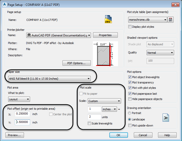
As you will notice, you are now editing a page setup in the Page Setup dialog box, just as you normally do if you were editing a layout’s page setup. First, create your standard 1:1 named page setups that plot 24x 36. Now, to do the half-size page setup set the appropriate settings for the right plotter, color/plot style table, Plot Option toggles, etc. Then, the key settings for plotting small are listed below:
- Plot scale
- Scale factor to 1 inches = 2 units
- Paper size
- ANSI full bleed B (11.00 x 17.00 inches)
- Plot offset

A little note regarding the Plot offset values. These values will vary based upon the size of your border and where you want it placed in your layout. There are no exact values that work for all companies.
Now, to associate a named page setup with a layout, make sure you are in the correct layout, and then simply double-click the named page setup. You will now notice that the named page setup appears next to the layout name in parentheses.

And that’s it! Now anytime you create a new drawing you will have the ability to plot big or small.
Article by Seth Cohen

by Alberto Freire | Aug 29, 2018 | Autodesk, BIM
The team here at Autodesk can’t wait to show off the Revit 2019.1 new features in the latest update released today. Following the course charted by the Revit Road Map, Revit 2019.1 includes new capabilities that help you connect, create, and, optimize.

Two Revit 2019.1 new features significantly deepen workflows with Autodesk BIM 360 project delivery and construction management software. When you first start up Revit 2019.1 you’ll notice how the new Revit Home screen makes it easier to navigate to and access your cloud models, providing BIM 360 Design users especially a more consistent and integrated experience. Big news is a new Site Collaboration workflow between Autodesk Civil 3D 2019.1, and Revit 2019.1 via BIM 360 Docs, that enables a connection between civil engineers and architects on large infrastructure projects. Additional Revit 2019.1 new features include free-form rebar aligned distribution and improvements to perspective views and dialog sizing. This update is available to subscribers and current maintenance plan customers via your Account portal or within Revit with the in-product Autodesk Desktop App.
Read on for more details about the top Revit 2019.1 new features
Connect
Our goal is to improve the processes by which you collaborate and exchange information. By building better experiences for sharing data across Autodesk tools and helping teams work together, we strive to help you get things done more efficiently.
Revit Home
Revit Home is a new user experience that modernizes the way you access, store, and share project information.
With Revit 2019.1, it is much easier for you to open your BIM 360 Design models directly from Revit Home. The BIM 360 project list is integrated into the left panel in the Home UI and you can quickly and easily browse BIM 360 folders to get to the model you need. With cloud models front and center, storing models in BIM 360 makes Revit workflows easier.

Easily open a Revit sample file from the updated Recent Files screen. Additionally, now as you click on a central file from Recent Files, Revit will create a local copy of the central model for you, adopting a consistent experience with BIM 360 Design models and reducing the risk of unwanted changes directly to the central files. With Revit Home, local copies are now hidden, and only central models show up on the recent files page, making your view more streamlined and easier to navigate. The new responsive Revit Home in the Revit 2019.1 release will improve model management, organization, and discovery.
Site Collaboration with Civil 3D
Site Collaboration is a Revit 2019.1 new feature that introduces unprecedented interoperability between Revit and Civil 3D. New workflows will help both save time and improve accuracy when you are transferring site information and project location data between project teams. You can easily link topography from Civil 3D into Revit using Autodesk Desktop Connector and BIM 360 Docs and will also be able to interact with this topography in Revit with surface hosting, tagging and scheduling. Civil 3D is included in the Autodesk Architecture, Engineering, and Construction Collection, which is great way to access Revit along with other essential tools at a great value.
 Civil 3D Publish to Revit workflow:
The site collaboration feature connects architects using Revit and engineers using Civil 3D via the BIM 360 document management module. When publishing Civil 3D to Revit, the workflow focuses on topography only. Engineers in Civil 3D can publish topography from Civil 3D, view the resulting data in BIM 360 document management, and then link the published data into Revit.
- In Civil 3D, from the tool space, select the surface for publish via Desktop Connector.
- Use BIM 360 , to check the topography in a 3D view and verify the correct data has published from Civil 3D.
- You’ll need to use the latest version of the free Desktop Connector to publish to Civil 3D surfaces for synchronizing the local files in BIM 360 Document Management.

Revit publish from Civil 3D Workflow:
In Revit, you will be able to easily link topography, which will help you to collaborate more effectively with civil engineers on the project.
- Browse to BIM 360 and link to the Civil 3D export.
- Civil 3D geolocation will try to place the model appropriately in Revit, but you also have the option to specify coordinates from Revit to update
- It is possible to spot dimension, add a building pad on the topography link and create a topography schedule in Revit with name, projected area, and surface area.
This workflow also supports sub regions and hosting railings. Sub regions are good for changing the surface material in Revit.
It is also possible to place elements on the topography – this will function as a link. Updates must be made in Civil 3D and edited and published again for use in Revit.
To work best, this workflow will require strategy for efficient navigation and linking and we recommend developing your BIM execution plan accordingly. Read more about this workflow on the Infrastructure Reimagined Blog

Making Updates to the Topography – Civil 3D and Revit Workflows:
This enhancement vastly improves the workflow for topography transfer from civil engineers to architects. You can make changes in Civil 3D and then upload as described in the previous process to BIM 360. In Revit, use reload or reload from and link topography again.

Support IFC Links from BIM 360 with Desktop Connector
With Revit 2019.1 IFC files can be linked in Revit using Desktop Connector and they will maintain their links. This feature will open doors for new IFC collaborative workflows.

Create
This category of Revit features is focused on delivering better tools, capabilities, and experiences central to authoring of project data, generating and using models.
Free Form Rebar Aligned Distribution
In Revit 2019.1 the Free Form Rebar tool can now be used to create rebar sets with planar bars distributed along the faces of a structural element and aligned to a distribution path. This new type of the free form rebar distribution increases 3D rebar modeling versatility and helps you define accurate reinforcement for standard and non-standard shapes of concrete elements.

As with the surface distribution type, you can model aligned distribution type by working in 3D views and selecting the structural element faces to which the bars are aligned. Bars in an aligned distribution are created at the intersection of each individual bar plane with the host surface. All the bars are planar, respect the cover of the host and are aligned to the distribution path.
- The path is the edge of an element that can host rebar. This can be selected directly when placing the set and represents the intersection of the faces in the Path Surface 1 and Path Surface 2 constraints.
- The bars in the set can be aligned to the path (it’s the default option) or can be parallel to the face selected in the align/close constraint.
- If the option to automatically close bars is enabled, then closed contour geometry can be obtained for each bar in an aligned distribution set. This option is enabled by default when placing a bar with the stirrup/tie style.
Get further detail on this feature in Tomasz Fudala’s post on BIM and Beam.
Move Pattern on Top of Wall
With Revit 2019.1 you have greater control over the look of a wall at every visible surface. You can now drag, rotate and align a model pattern on a painted top surface of a wall, enabling you to control alignment of pattern tile location on all faces of a wall.

Import Double Fill Patterns
With Revit 2019 you got double-fill patterns. Now with Revit 2019.1, importing patterns from AutoCAD to Revit is easier and requires less management. When importing a double fill pattern (a hatch with a background color) from AutoCAD to Revit, you will now see the background color on import. You can explode the AutoCAD hatch in Revit, and a Revit pattern with a background is created as a single object, removing the need to manage two coincident filled regions.

Optimize
Optimize means several things in the context of Revit – it’s how we can improve your ease in working by making the software work better and by improving your interaction with the software. It’s also in delivering tools that you can use to analyze and conduct simulations to get the insights you need to make the best design decisions.
Improved Work with Perspective Views
Revit 2019.1 includes a set of enhancements to perspective views that dramatically improve the modeling process in 3D views.
- In behavior consistent with orthographic view, when orienting a 3D view or perspective view to an elevation, section, or floor plan, the view orients to that camera position and the section box is activated and cuts the model.

- When you duplicate a perspective view, all relevant view attributes, such as camera position and zoom, are now transferred to the new view.
- Now, locked perspective views cannot be rotated, or the camera moved.
- The Zoom in Region tool moves the camera instead of zooming on an uncropped perspective view. This allows Zoom in Region to be used as a navigation tool.
- The Reset Crop Region tools enable crop visibility, so you can see the result of your changes.
- The behavior of the keyboard modifier for Orbit/Pan/Zoom has been refined. You can switch between Orbit and Pan using the center mouse button and the Shift key.
- Panning and navigation in uncropped perspective views is now more responsive and faster.
We’re confident these improvements will help you work more easily and faster in immersive 3D with perspective views.
Section View Align and Snapping
In Revit 2019.1 you can use the Align command to select the line for a section view and use it as the reference for alignment or as the object to align. For example, you can align a section line with an angled wall.

In addition, snaps are enabled for section lines, so you can snap while moving a section line, or snap to a section line during the placement of another element.
These enhancements support precise positioning of section views to make it easier and faster to get your work done.
Resizable Dialogs
In response to customer requests submitted via the Revit Ideas page, Revit 2019.1 new features include the ability to resize the Go To View dialog and the Add View to Sheet dialog. You can drag the corners or edges of these dialogs to resize them to display long lists of views and long view names that previously did not fit in the dialog boxes. Letting you see the entire view name continuously on the screen helps you work easier and faster with dialog boxes.

The Revit 2019.1 update for subscribers is here and available on your Account page now. With our move to more agile development and a subscription model, we are working to ensure that Revit delivers more frequent value with multiple releases per year. Revit 2019.1 new features represent progress along the Revit road map of growth and innovation that helps you create models, work more efficiently, and connect teams and data.


 Civil 3D Publish to Revit workflow:


