Archibus by Eptura V.2024.04 Release

Archibus by Eptura V.2024.04 Release

A new release of Archibus by Eptura is out. Here’s what’s new in V.2024.04:

Space

BIM Viewer Space Planning

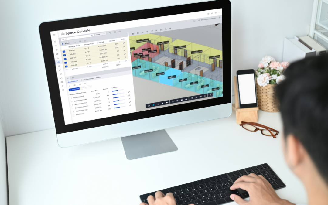
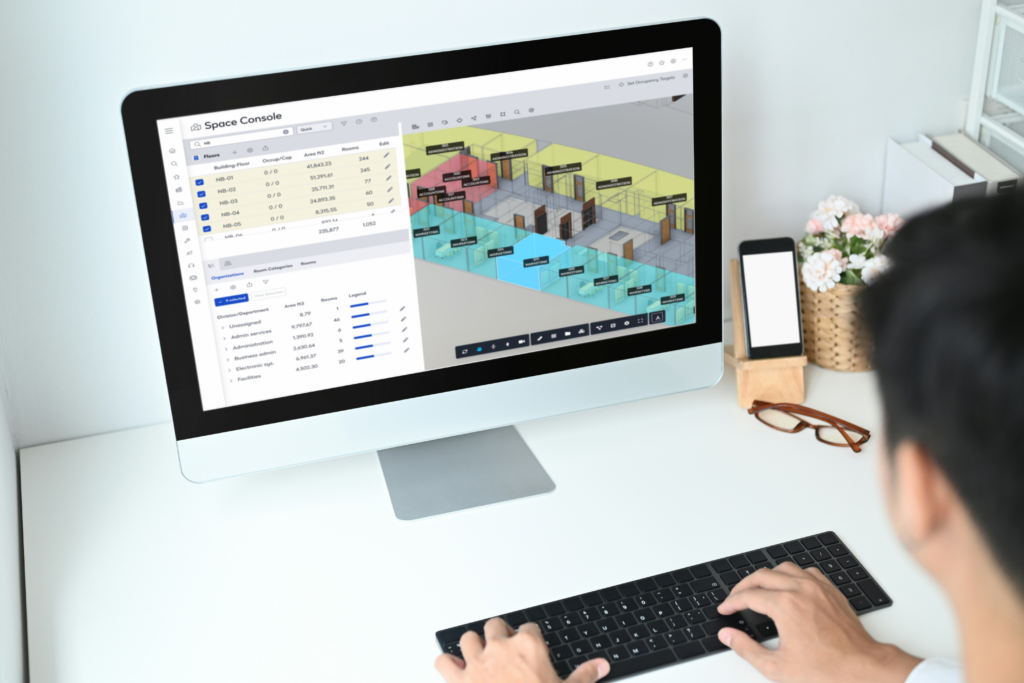
  • The BIM Viewer was extended into the Space Console.
  • In the Space Console, Space Managers use the BIM visualization to assign people to rooms and report on occupancy.

Floorplan viewer

The Doors are no longer displaying as arcs

BIM Viewer

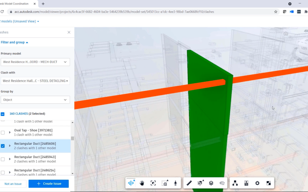
  • Linked Models: Support for linked models stored in Autodesk Construction Cloud:
    • Support for linked models stored in Autodesk Construction Cloud is no longer a proof-of-concept and it is considered a supported feature
  • Catalog BIM Models: Cloud cataloging for spaces and assets supports additional fields:
    • Catalog additional fields for equipment and furniture based on BIM parameters to Archibus fields mapping
    • Infer rooms codes for equipment and furniture in linked models
    • Catalog Room Standards, Room Use for rooms
  • The BIM Viewer was upgraded to the latest Autodesk Platform Services version – 7.100.1.

Maintenance

  • Improved loading performance of the Maintenance Console.
    • Data categories are loaded asynchronously.
    • Improved loading time of the work request details view.
  • Craftsperson Performance Report: Added the option to export to Excel.
  • Maintenance Console: Work Request Details view: Supervisors and technicians can remove work logs.

Onsite

Parts Inventory:

  • Technicians can search the parts inventory
  • Technicians can log the parts used for work requests, including purchased parts

Workplace

  • The Workplace application retrieves the first available floor and available spaces faster, resulting in an increase in performance when booking workspaces
  • Team members have the option to make one-time workspace bookings that take into account the team’s week-days in office.
    • In the Space Console, Space Managers can set the days of the week when teams are going to their office and are not working remotely
    • In Workplace, team-members use a filter on the Team Code and a highlight to identify the available workspaces for the same days of the week when the team goes to office.
  • Multiple accessibility and UX improvements. For example:
    • Enhancements to accessibility for visually impaired employees and guests who might need to enlarge the application 400%
    • UX enhancements for selecting requestors

Web Central

  • Improved loading performance of home pages
  • Database Update Wizard (DUW): Add null check for SQL_NUMERIC type when performing DUW comparison

SmartClient Extension for Revit

  • Linked Models: Infer room codes when cataloging assets or furniture stored in a linked assets (MEP) model.
  • 2D Publishing: Switched from custom to native Revit APIs which optimizes file size, improves data and error handling
  • Serraview to Archibus converter increased stability


The Best Way to Get Archibus

If you’re new to Archibus or want to get this software today, our team at Robotech can help. We offer comprehensive entry-level basics training, and we sell Archibus software directly to companies across the country. We are a gold partner of Archibus, and we’ll ensure your team is fully set up and comfortable with the software before we consider the job “done”.
We have a few Archibus packages that we offer, and we can provide a free trial for you to test it before you buy. Within a few minutes, you’ll see how helpful this software is in maintaining your healthcare compliance accreditation.

Schedule a call to get started today.


AutoCAD Tips: Mastering Annotative Objects for Text and Dimensions in AutoCAD

Tutorial Objectives:
This tutorial will teach you how to use annotative text and dimensions in AutoCAD. Annotative objects automatically scale based on the viewport scale, allowing you to maintain consistent text and dimension sizes across multiple viewports in a layout.

Understanding Annotative Objects

What are Annotative Objects?
In AutoCAD, annotative objects are designed to be scaled automatically based on the scale of your drawing or viewport. This feature is especially useful when working with text, dimensions, and hatches that need to appear at a consistent size on printed drawings.

Why Use Annotative Objects?
– Eliminates the need to create multiple copies of text and dimensions for different scales.
– Ensures that annotations are readable and consistent in different viewports.
– Saves time and reduces errors in scaling manually.

Creating Annotative Text

Step 1: Define Annotative Text Style
1. Type `STYLE` and press Enter to open the Text Style Manager.
2. Click New, name the text style as `Annotative Text`, and check the box labeled Annotative
3. Set the font and size (e.g., 1/8” or 3 mm depending on your units).
4. Click Apply and then Close.

Step 2: Place Annotative Text
1. Type `TEXT` and press Enter.
2. Specify a start point and enter your text (e.g., “Annotative Text Example”).
3. Notice the Annotative Icon (a small scale symbol) next to the text, indicating that it’s annotative.

Step 3: Assign Annotation Scale
1. Select the text object.
2. In the Properties panel, find the Annotative Scale section.
3. Add multiple scales (e.g., 1:1, 1:2, 1:4) using the Annotation Scale dropdown.

Tips:
Use the `ANNOAUTOSCALE` command and set it to 1 to automatically add the current annotation scale to all annotative objects.

Creating Annotative Dimensions

Step 1: Define Annotative Dimension Style
1. Type `DIMSTYLE` and press Enter to open the Dimension Style Manager.
2. Click New, name it `Annotative Dim`, and check the box labeled Annotative.
3. Go to the Text tab and set the text height to 1/8″ (or 3 mm).
4. In the Fit tab, ensure that Scale dimensions to layout is selected.
5. Click OK and Set Current, then close the dialog.

Step 2: Place Annotative Dimensions
1. Type `DIMLINEAR` and press Enter.
2. Select two points on the rectangle to place the dimension.
3. The dimension will automatically be assigned the current annotation scale.

Testing Annotative Scaling in Viewports

Step 1: Create Layout Viewports
1. Go to the Layout tab and type `MV` (for Make Viewport).
2. Draw two viewports side by side on the layout.

Step 2: Set Different Scales for Each Viewport
1. Click on the first viewport and set its scale to 1:1.
2. Click on the second viewport and set its scale to 1:2.

Step 3: Observe the Annotative Objects
– The text and dimensions should automatically resize based on the viewport scale, appearing consistent and readable in both viewports.

Tutorial Tips:
If the annotations don’t display correctly, use the command `ANNOUPDATE` to refresh them.

Common Issues and Troubleshooting

1. Annotations Not Scaling Properly:
– Ensure the objects are set as annotative in their properties.
– Verify that the annotation scales have been applied correctly.

2. Text or Dimensions Not Visible:
– Check if the viewport scale is listed in the object’s annotation scale list.
– Use `ANNOALLVISIBLE` and set it to 1 to display all annotative objects, regardless of the current scale.

3. Text Overlapping or Cluttered:
– Adjust the annotation scales or reposition objects to avoid overlaps in different viewports.

By mastering annotative text and dimensions, you can ensure consistent annotation sizes across different scales and viewports, making your drawings more professional and easier to read. This is a powerful skill for anyone looking to streamline their AutoCAD workflow.

Interested in learning more AutoCAD content?

Revit Tips: Setting Up Phases in Revit for Renovation Projects

Revit Tips: Setting Up Phases in Revit for Renovation Projects

Phasing in Revit is an essential tool for projects that involve renovation or construction in stages. This feature allows you to differentiate between existing, demolished, and new construction elements within a project. In this tutorial, we’ll walk through how to set up and use phasing effectively for a simple renovation project.

Tutorial Objectives:

– Understand the basics of Revit phasing.
– Set up phases in a Revit project.
– Assign elements to different phases (Existing, Demolished, New).
– Adjust phase filters to control the visibility of elements in views.
– Create a phase-specific view (Existing Plan, Demolition Plan, New Construction Plan).

Step 1: Understanding Phases in Revit

Revit uses phases to manage different stages of a project’s lifecycle. By default, Revit includes two phases:

Existing: Represents the current state before any new work begins.
New Construction: Represents elements that are added during the project.

You can add more phases if needed (e.g., “Demolition”), but in most renovation projects, these two are sufficient.

Step 2: Setting Up Phases in Your Project

  1. Open your Revit project.
  2. Go to the Manage tab on the ribbon and click on Phases.
  3. In the Phases dialog box, you will see two default phases: Existing and New Construction.
  4. You can add more phases by clicking Insert if your project requires it (e.g., adding a “Demolition” phase).

Step 3: Assigning Phases to Elements

Every element in Revit can be assigned a specific phase:

  1. Select an element in your project (e.g., a wall).
  2. In the Properties palette, find the Phasing section.
  3. Set the Phase Created property. For existing elements, set it to Existing.
  4. For new elements, set the Phase Created to New Construction.
  5. If an element needs to be demolished, set Phase Created to Existing and Phase Demolished to New Construction.

Step 4: Using Phase Filters in Views

Phase filters control the display of elements based on their phase status:

  1. Select a floor plan view (e.g., “Level 1”).
  2. In the Properties palette, find the Phase and Phase Filter settings.

Phase: Set this to the phase you want the view to represent (e.g., “Existing” or “New Construction”).
Phase Filter: Choose a filter like Show All, Show New, or Show Demo based on what you want to display.

  1. Try switching between different phase filters to see how the elements change visibility.

Step 5: Creating Phase-Specific Views

To effectively communicate your renovation project, set up separate views for each phase:

  1. Duplicate your floor plan view (Right-click the view > Duplicate View > Duplicate).
  2. Rename the views according to the phase (e.g., “Level 1 – Existing,” “Level 1 – Demolition,” “Level 1 – New Construction”).
  3. Set the Phase and Phase Filter properties for each view:

– For Existing views, set the Phase to “Existing” and the Phase Filter to Show Complete.
– For Demolition views, set the Phase to “New Construction” and the Phase Filter to Show Demo.
– For New Construction views, set the Phase to “New Construction” and the Phase Filter to Show New.

Step 6: Annotating Phase Views

  1. Add tags, dimensions, and annotations as needed in each view.
  2. Ensure that demolished elements are properly indicated with a dashed line or other visual style (controlled by the Phase Filter settings).

Step 7: Creating a Phase Schedule (Optional)

You can also create schedules that list elements based on their phase:

  1. Go to the View tab and click on Schedules > Schedule/Quantities.
  2. Choose a category (e.g., Walls) and click OK.
  3. In the Schedule Properties dialog, add the field Phase Created.
  4. Use filters to separate existing, demolished, and new elements.

Tips:

– Use graphics overrides in the Phases dialog to customize how different phases appear (e.g., existing elements in gray, demolished in dashed lines).
– Check the Phase Filter settings carefully, as they control what elements are visible in each view.

Interested in learning more Revit content?

AutoCAD Tip: New in 2025 are Tech Previews – Try the latest Block Object Detection

AutoCAD Tip: New in 2025 are Tech Previews – Try the latest Block Object Detection

Tech Previews, also referred to as technical or technology previews, offer you the opportunity to access new features in AutoCAD before they’re officially released. By participating in Tech Previews, you can explore and test out the functionality of these new features and provide valuable feedback to the AutoCAD product team.

During a Tech Preview, the preview features are fully functional and ready to be used. Since these features are still under development, additional capabilities and improvements may be available for testing. This provides you a chance to evaluate how these features can benefit your workflows and projects.

Unlike Beta programs, Tech Previews are open to everyone, allowing active participation and contribution to the ongoing improvement of the feature’s capabilities. Your feedback is important in shaping the final version of the feature.

AutoCAD is dedicated to continuously improve and evolve the preview feature until it reaches a stage where it’s ready to be released as a regular feature, thereby transitioning out of the Tech Preview phase.

AutoCAD 2025 includes a technology preview that uses machine learning to scan your drawing for objects that can be converted into blocks.

When you start Object Detection, the drawing’s geometry is sent to the AutoCAD machine learning service for recognition. Once the service has analyzed the drawing, the palette will notify you if any objects have been detected that can be converted to blocks. To further inspect and assess the identified instances, click Review Objects.

In review mode, the Detection toolbar is displayed at the top of the drawing window. This toolbar provides various options for navigating and managing detection results. The detection results are grouped into sets of similar objects. A set represents a group of similar detected objects that can be converted into instances of a single block.

Within each set, the primary instance (outlined by a blue border) serves as the block definition when converting into a new block. Alternatively, if you choose to convert into an existing block, the primary instance is used to define the insertion scale and rotation.

You may encounter incorrect sets or instances during detection review. In the following example, a similar object is not detected and included in the set. You can report this error using the Detection toolbar. By reporting errors, you contribute to improving the overall performance and accuracy of the machine learning service.

Key Considerations

Object Detection is a technology preview, which means that the detection capability and functionality will be further enhanced and improved over time.

It’s important to note that Object Detection is optimized for plan-view drawings. The types of objects that AutoCAD can detect are continuously expanding. Currently, Object Detection is best at recognizing the following objects:

  • Single-swing doors
  • Double-swing doors
  • Toilets
  • Bathtubs
  • Urinals
  • Generic lighting symbols
Note: Object Detection relies on machine learning algorithms, so the results may not always be completely accurate or comprehensive.

To optimize detection accuracy as we continue to improve the machine learning algorithm, it’s recommended to set your drawing to real-world units before you start the detection.

While in review mode, the following commands are temporarily blocked:

  • BEDIT
  • COMPARE
  • COUNT
  • COUNTLIST
  • PLOT
  • PUBLISH
  • REFEDIT
  • TRACE
  • XCOMPARE
Simplify building navigation with Mapsted’s Wayfinding technology

Simplify building navigation with Mapsted’s Wayfinding technology

Wayfinding — guiding people through your space with turn-by-turn navigation — can help to welcome guests to your buildings and enable employees to find unfamiliar locations.

Integrating wayfinding into your Archibus deployment can have several uses. For example:

  • If you have a campus with multiple buildings, employees can access directions from a point in one building to a point in another building.
  • For booked working spaces and meeting rooms, employees want directions that guide them to the location so that they can easily find the booked room and arrive on time.
  • For planning purposes, employees want to see the fastest path to a working space that they booked or a meeting that they must attend.
  • When Workplace is deployed on a lobby kiosk, building visitors can access routes to locations in an unfamiliar building.
  • For the Workplace mobile app, navigation is supported through QR code scanning.

Wayfinding Button

To support these types of scenarios, Workplace can integrate Mapsted’s wayfinding technology by providing a Wayfinding button on the following Workplace pages:

  • Find People and Places
  • Meeting Space Booking Detail
  • Workspace Booking Details

If you have an Archibus Wayfinding license, but you do not have a Mapsted floor plan for a floor, the Wayfinding icon appears in gray, as shown on the below Workspace Booking Details page.

Mapsted Interface

Once you select Workplace’s Wayfinding button, the Mapsted interface overlays Workplace. You can then use the Mapsted interface to enter a destination. For example, in the below image, the user has entered start and destination locations within the same floor, and Mapsted has outlined the route in blue on the floor plan and provided turn-by-turn written instructions.

When through, you can select the Return to Workplace button in the upper right corner to return to the Workplace interface.

Requirements

Wayfinding is compatible with both SaaS and non-SaaS instances. For non-SaaS instances, your company’s IT policy must allow the Workplace application to connect to the external API’s defined in the AbWayfinding.MapstedUrl and AbWayfinding.MapstedSearchUrl application parameters, described below.

In order to integrate the wayfinding features:

  • The Archibus Wayfinding license must be enabled.
  • You must have a license to access or use Mapsted services during the current subscription term.
  • You must have created digital maps stored in Mapsted with room-level attributes including ”floorId”,”buildingId”,”propertyId” that enable the location to be displayed in the Archibus Wayfinding page using the Mapstead API.
  • In order to enable building-to-building navigation within a site, the buildings within a single Archibus site should be configured in a single property in Mapsted.
  • You must set the below application parameters.

Application Parameters

Set the parameters with: System / Archibus Administrator – Application Configuration / Configure Application Parameters.

AbWayfinding.MapstedUrl

This URL is used in Workplace to redirect to Mapsted’s Wayfinding feature. The default value works without configuration. The values in the <> brackets will be derived from Workplace.

The default value is:
https://maps.mapsted.com/<propertyId>?building=<bl_id>&floor=<fl_id>&entity=<rm_id>

AbWayfinding.MapstedSearchUrl

This URL is used in Workplace to find the Mapsted attributes for a specific room. The values in the <> brackets will be filled out in Workplace. The default value work without configuration, except that you must set “provider” with your company’s unique Mapsted ID.

The default value is:
https://public.mapsted.com/api/v1/integration/search?provider=archibus&property=<bl_id>&longName=<rm_id>

We at Robotech understand the challenges organizations face in optimizing navigation within their facilities.

If you want to reach us for any questions, please send us a message below or call 201-792-6300 to to schedule a demo, or email the team at [email protected].