AutoCAD Tutorial: Advanced Layer Management Techniques

AutoCAD Tutorial: Advanced Layer Management Techniques

Welcome to our tutorial on advanced layer management techniques in AutoCAD! Whether you’re a seasoned professional or a beginner looking to improve your drafting efficiency, mastering layer management can significantly enhance your workflow. In this guide, we’ll explore layer filters, layer states, and property overrides to help you organize your drawings like a pro.

Why Advanced Layer Management Matters


In complex drawings, managing layers can become overwhelming. Advanced techniques like layer filters, layer states, and property overrides allow you to:

– Quickly isolate and work with specific layers.

– Save and restore layer configurations for different tasks.

– Temporarily override layer properties without altering the original settings.

Let’s dive into each of these techniques!

  1. Using Layer Filters

Layer filters help you organize and display only the layers you need at any given time. This is especially useful in drawings with dozens or hundreds of layers.


Steps to Create a Layer Filter:

  1. Open the Layer Properties Manager:

– Type `LA` in the command line and press Enter.

– Alternatively, find it in the Home tab under the Layers panel.

  1. Create a New Filter:

– In the Layer Properties Manager, click the New Property Filter button (funnel icon).

– Name your filter (e.g., “Electrical Layers”).

  1. Set Filter Criteria:

– Use the filter dialog to specify criteria like Layer Name, Color, or Line Type.

– For example, filter layers with names containing “ELEC” for electrical components.

  1. Apply the Filter:

– Once created, the filter will display only the layers that match your criteria.

– You can toggle the filter on or off as needed.


![Layer Filter Example](image-link-here)

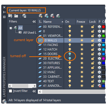
*Example: A layer filter isolating electrical layers.*

  1. Saving and Restoring Layer States


Layer states allow you to save the current visibility, color, line type, and other properties of layers. You can restore these states later, making it easy to switch between different views or configurations.


Steps to Save a Layer State:

  1. Configure Your Layers:

– Adjust layer properties (e.g., turn off layers, change colors) to your desired setup.

  1. Open the Layer States Manager:

– Type `LAYERSTATE` in the command line and press Enter.

– Alternatively, find it in the Home tab under the Layers panel.

  1. Create a New Layer State:

– Click New and give your state a name (e.g., “Floor Plan View”).

– Choose which properties to save (e.g., On/Off, Color, Line Type).

  1. Restore a Layer State:

– To restore a saved state, open the Layer States Manager, select the state, and click Restore.


![Layer States Example](image-link-here)

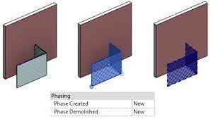
*Example: Saving and restoring a layer state for a floor plan view.*

  1. Using Property Overrides

Property overrides allow you to temporarily change the appearance of layers in specific viewports without altering the original layer properties. This is particularly useful for creating presentation drawings.


Steps to Apply Property Overrides:

  1. Switch to a Layout Tab:

– Click on a layout tab to access paper space.

  1. Enter a Viewport:

– Double-click inside a viewport to enter model space.

  1. Open the Layer Properties Manager:

– Type `LA` and press Enter.

  1. Override Layer Properties:

– In the Layer Properties Manager, look for the “VP” columns (Viewport Overrides).

– Click on a property (e.g., Color, Line Type) to override it for the current viewport.

  1. Exit the Viewport:

– Double-click outside the viewport to return to paper space.

![Property Overrides Example](image-link-here)

*Example: Overriding layer colors in a viewport for a presentation drawing.*

Tips for Effective Layer Management

Use Descriptive Layer Names: Avoid generic names like “Layer1.” Instead, use names like “Walls,” “Doors,” or “Electrical.”

Group Related Layers: Use layer filters or prefixes to group similar layers (e.g., “A-Walls,” “A-Doors” for architectural layers).

Save Multiple Layer States: Create layer states for different tasks, such as “Editing,” “Printing,” or “Presentation.”

Leverage Templates: Save your layer setups in a template file (`DWT`) to reuse them in future projects.

Conclusion

By mastering advanced layer management techniques in AutoCAD, you can streamline your workflow, reduce errors, and create more organized drawings. Whether you’re using layer filters to isolate specific elements, saving layer states for quick configuration changes, or applying property overrides for presentations, these tools will help you work smarter, not harder.

Feel free to experiment with these techniques and incorporate them into your daily workflow. Happy drafting!


Revit Tutorial: Using View Range Settings in Revit to Control Visibility in Floor Plan Views

Revit Tutorial: Using View Range Settings in Revit to Control Visibility in Floor Plan Views

Welcome to this beginner-friendly tutorial on using View Range settings in Autodesk Revit! View Range is a powerful tool that allows you to control which elements are visible in your floor plan views. By the end of this tutorial, you’ll understand how to adjust these settings to display exactly what you need in your drawings.

What is View Range?

In Revit, the View Range determines how much of the model is visible in a floor plan view. It defines the vertical range (height) of the view and controls which elements are cut, visible, or hidden. Think of it as a “slice” through your building model at a specific height.

Key Components of View Range

The View Range settings consist of four primary planes:

  1. Primary Range

Top: Defines the upper limit of the view.

Cut Plane: Defines the height at which elements are “cut” (e.g., walls, doors, windows).

Bottom: Defines the lower limit of the view.

  1. View Depth: Extends below the Bottom plane to show additional elements (e.g., foundations or floor slabs).

Step-by-Step Guide to Adjusting View Range


Step 1: Open a Floor Plan View

  1. Open your Revit project.
  2. Navigate to the floor plan view you want to adjust.

Step 2: Access View Range Settings

  1. In the Properties palette, scroll down to the Extents section.
  2. Click on View Range to open the View Range dialog box.

Step 3: Understand the View Range Dialog Box

The dialog box will display the following fields:

Top: Set this to the highest level you want to see in the view (e.g., the level above).

Cut Plane: Set this to the height where elements are cut (typically 4 feet for floor plans).

Bottom: Set this to the lowest level you want to see in the view (e.g., the current level).

View Depth: Set this to extend below the Bottom plane if you want to see additional elements.

Step 4: Adjust the Settings

  1. Set the Cut Plane: For most floor plans, set the Cut Plane to 4 feet (1200 mm) to cut through doors and windows.
  2. Adjust the Top and Bottom: Set the Top to the level above and the Bottom to the current level.
  3. Extend the View Depth: If you want to see elements below the floor (e.g., foundations), set the View Depth below the Bottom plane.

Step 5: Apply and Check the Results

  1. Click OK to apply the settings.
  2. Review your floor plan to ensure the desired elements are visible.

Tips for Beginners 

Experiment: Don’t be afraid to adjust the settings and see how they affect your view.

Use Defaults: Start with the default settings and tweak them as needed.

Check Visibility Graphics: If elements are still not visible, ensure they are not hidden in the Visibility/Graphics settings.

Visual Aid

The images below are an example of how the View Range dialog box looks and how it affects a floor plan view: 

Conclusion 

Mastering the View Range settings in Revit is essential for creating accurate and clear floor plan views. By following this tutorial, you should now feel confident in adjusting these settings to control the visibility of elements in your projects.

Happy modeling!

AutoCAD Tips: Mastering Annotative Objects for Text and Dimensions in AutoCAD

Tutorial Objectives:
This tutorial will teach you how to use annotative text and dimensions in AutoCAD. Annotative objects automatically scale based on the viewport scale, allowing you to maintain consistent text and dimension sizes across multiple viewports in a layout.

Understanding Annotative Objects

What are Annotative Objects?
In AutoCAD, annotative objects are designed to be scaled automatically based on the scale of your drawing or viewport. This feature is especially useful when working with text, dimensions, and hatches that need to appear at a consistent size on printed drawings.

Why Use Annotative Objects?
– Eliminates the need to create multiple copies of text and dimensions for different scales.
– Ensures that annotations are readable and consistent in different viewports.
– Saves time and reduces errors in scaling manually.

Creating Annotative Text

Step 1: Define Annotative Text Style
1. Type `STYLE` and press Enter to open the Text Style Manager.
2. Click New, name the text style as `Annotative Text`, and check the box labeled Annotative
3. Set the font and size (e.g., 1/8” or 3 mm depending on your units).
4. Click Apply and then Close.

Step 2: Place Annotative Text
1. Type `TEXT` and press Enter.
2. Specify a start point and enter your text (e.g., “Annotative Text Example”).
3. Notice the Annotative Icon (a small scale symbol) next to the text, indicating that it’s annotative.

Step 3: Assign Annotation Scale
1. Select the text object.
2. In the Properties panel, find the Annotative Scale section.
3. Add multiple scales (e.g., 1:1, 1:2, 1:4) using the Annotation Scale dropdown.

Tips:
Use the `ANNOAUTOSCALE` command and set it to 1 to automatically add the current annotation scale to all annotative objects.

Creating Annotative Dimensions

Step 1: Define Annotative Dimension Style
1. Type `DIMSTYLE` and press Enter to open the Dimension Style Manager.
2. Click New, name it `Annotative Dim`, and check the box labeled Annotative.
3. Go to the Text tab and set the text height to 1/8″ (or 3 mm).
4. In the Fit tab, ensure that Scale dimensions to layout is selected.
5. Click OK and Set Current, then close the dialog.

Step 2: Place Annotative Dimensions
1. Type `DIMLINEAR` and press Enter.
2. Select two points on the rectangle to place the dimension.
3. The dimension will automatically be assigned the current annotation scale.

Testing Annotative Scaling in Viewports

Step 1: Create Layout Viewports
1. Go to the Layout tab and type `MV` (for Make Viewport).
2. Draw two viewports side by side on the layout.

Step 2: Set Different Scales for Each Viewport
1. Click on the first viewport and set its scale to 1:1.
2. Click on the second viewport and set its scale to 1:2.

Step 3: Observe the Annotative Objects
– The text and dimensions should automatically resize based on the viewport scale, appearing consistent and readable in both viewports.

Tutorial Tips:
If the annotations don’t display correctly, use the command `ANNOUPDATE` to refresh them.

Common Issues and Troubleshooting

1. Annotations Not Scaling Properly:
– Ensure the objects are set as annotative in their properties.
– Verify that the annotation scales have been applied correctly.

2. Text or Dimensions Not Visible:
– Check if the viewport scale is listed in the object’s annotation scale list.
– Use `ANNOALLVISIBLE` and set it to 1 to display all annotative objects, regardless of the current scale.

3. Text Overlapping or Cluttered:
– Adjust the annotation scales or reposition objects to avoid overlaps in different viewports.

By mastering annotative text and dimensions, you can ensure consistent annotation sizes across different scales and viewports, making your drawings more professional and easier to read. This is a powerful skill for anyone looking to streamline their AutoCAD workflow.

Interested in learning more AutoCAD content?

Revit Tips: Setting Up Phases in Revit for Renovation Projects

Revit Tips: Setting Up Phases in Revit for Renovation Projects

Phasing in Revit is an essential tool for projects that involve renovation or construction in stages. This feature allows you to differentiate between existing, demolished, and new construction elements within a project. In this tutorial, we’ll walk through how to set up and use phasing effectively for a simple renovation project.

Tutorial Objectives:

– Understand the basics of Revit phasing.
– Set up phases in a Revit project.
– Assign elements to different phases (Existing, Demolished, New).
– Adjust phase filters to control the visibility of elements in views.
– Create a phase-specific view (Existing Plan, Demolition Plan, New Construction Plan).

Step 1: Understanding Phases in Revit

Revit uses phases to manage different stages of a project’s lifecycle. By default, Revit includes two phases:

Existing: Represents the current state before any new work begins.
New Construction: Represents elements that are added during the project.

You can add more phases if needed (e.g., “Demolition”), but in most renovation projects, these two are sufficient.

Step 2: Setting Up Phases in Your Project

  1. Open your Revit project.
  2. Go to the Manage tab on the ribbon and click on Phases.
  3. In the Phases dialog box, you will see two default phases: Existing and New Construction.
  4. You can add more phases by clicking Insert if your project requires it (e.g., adding a “Demolition” phase).

Step 3: Assigning Phases to Elements

Every element in Revit can be assigned a specific phase:

  1. Select an element in your project (e.g., a wall).
  2. In the Properties palette, find the Phasing section.
  3. Set the Phase Created property. For existing elements, set it to Existing.
  4. For new elements, set the Phase Created to New Construction.
  5. If an element needs to be demolished, set Phase Created to Existing and Phase Demolished to New Construction.

Step 4: Using Phase Filters in Views

Phase filters control the display of elements based on their phase status:

  1. Select a floor plan view (e.g., “Level 1”).
  2. In the Properties palette, find the Phase and Phase Filter settings.

Phase: Set this to the phase you want the view to represent (e.g., “Existing” or “New Construction”).
Phase Filter: Choose a filter like Show All, Show New, or Show Demo based on what you want to display.

  1. Try switching between different phase filters to see how the elements change visibility.

Step 5: Creating Phase-Specific Views

To effectively communicate your renovation project, set up separate views for each phase:

  1. Duplicate your floor plan view (Right-click the view > Duplicate View > Duplicate).
  2. Rename the views according to the phase (e.g., “Level 1 – Existing,” “Level 1 – Demolition,” “Level 1 – New Construction”).
  3. Set the Phase and Phase Filter properties for each view:

– For Existing views, set the Phase to “Existing” and the Phase Filter to Show Complete.
– For Demolition views, set the Phase to “New Construction” and the Phase Filter to Show Demo.
– For New Construction views, set the Phase to “New Construction” and the Phase Filter to Show New.

Step 6: Annotating Phase Views

  1. Add tags, dimensions, and annotations as needed in each view.
  2. Ensure that demolished elements are properly indicated with a dashed line or other visual style (controlled by the Phase Filter settings).

Step 7: Creating a Phase Schedule (Optional)

You can also create schedules that list elements based on their phase:

  1. Go to the View tab and click on Schedules > Schedule/Quantities.
  2. Choose a category (e.g., Walls) and click OK.
  3. In the Schedule Properties dialog, add the field Phase Created.
  4. Use filters to separate existing, demolished, and new elements.

Tips:

– Use graphics overrides in the Phases dialog to customize how different phases appear (e.g., existing elements in gray, demolished in dashed lines).
– Check the Phase Filter settings carefully, as they control what elements are visible in each view.

Interested in learning more Revit content?

AutoCAD Tip: New in 2025 are Tech Previews – Try the latest Block Object Detection

AutoCAD Tip: New in 2025 are Tech Previews – Try the latest Block Object Detection

Tech Previews, also referred to as technical or technology previews, offer you the opportunity to access new features in AutoCAD before they’re officially released. By participating in Tech Previews, you can explore and test out the functionality of these new features and provide valuable feedback to the AutoCAD product team.

During a Tech Preview, the preview features are fully functional and ready to be used. Since these features are still under development, additional capabilities and improvements may be available for testing. This provides you a chance to evaluate how these features can benefit your workflows and projects.

Unlike Beta programs, Tech Previews are open to everyone, allowing active participation and contribution to the ongoing improvement of the feature’s capabilities. Your feedback is important in shaping the final version of the feature.

AutoCAD is dedicated to continuously improve and evolve the preview feature until it reaches a stage where it’s ready to be released as a regular feature, thereby transitioning out of the Tech Preview phase.

AutoCAD 2025 includes a technology preview that uses machine learning to scan your drawing for objects that can be converted into blocks.

When you start Object Detection, the drawing’s geometry is sent to the AutoCAD machine learning service for recognition. Once the service has analyzed the drawing, the palette will notify you if any objects have been detected that can be converted to blocks. To further inspect and assess the identified instances, click Review Objects.

In review mode, the Detection toolbar is displayed at the top of the drawing window. This toolbar provides various options for navigating and managing detection results. The detection results are grouped into sets of similar objects. A set represents a group of similar detected objects that can be converted into instances of a single block.

Within each set, the primary instance (outlined by a blue border) serves as the block definition when converting into a new block. Alternatively, if you choose to convert into an existing block, the primary instance is used to define the insertion scale and rotation.

You may encounter incorrect sets or instances during detection review. In the following example, a similar object is not detected and included in the set. You can report this error using the Detection toolbar. By reporting errors, you contribute to improving the overall performance and accuracy of the machine learning service.

Key Considerations

Object Detection is a technology preview, which means that the detection capability and functionality will be further enhanced and improved over time.

It’s important to note that Object Detection is optimized for plan-view drawings. The types of objects that AutoCAD can detect are continuously expanding. Currently, Object Detection is best at recognizing the following objects:

  • Single-swing doors
  • Double-swing doors
  • Toilets
  • Bathtubs
  • Urinals
  • Generic lighting symbols
Note: Object Detection relies on machine learning algorithms, so the results may not always be completely accurate or comprehensive.

To optimize detection accuracy as we continue to improve the machine learning algorithm, it’s recommended to set your drawing to real-world units before you start the detection.

While in review mode, the following commands are temporarily blocked:

  • BEDIT
  • COMPARE
  • COUNT
  • COUNTLIST
  • PLOT
  • PUBLISH
  • REFEDIT
  • TRACE
  • XCOMPARE
Use ETransmit to send files to AutoCAD files

Use ETransmit to send files to AutoCAD files

If you need to send your AutoCAD drawings to someone else, use ETransmit to bundle up your files and include references (XREFs).

In AutoCAD with the drawing open that you want to ETransmit.

1. Save the drawing.
2. Enter ETRANSMIT at the command line and hit enter.
3. On the Create Transmittal dialog check or uncheck the items you do not need or want to package up.
4. Click to edit the “Transmittal setups…”
5. Click Modify.
6. On the Modify Transmittal Setup dialog insure it’s set to ZIP for a smaller file size
7. Click the ellipses “…” button the change the folder the .zip file will be saved into by default.
8. Click the dropdown so it will “Prompt for a filename” if desired.
9. Select the radio button to “Place all files in one folder”.

There are many other options too, however I do not recommend using the bind option as it can create one very large file that may be terribly slow.

Click Ok and close out of the dialogs and get back to the ETransmit dialog